
ball mill drive design manufacturer Grasping strong production capability, advanced research strength and excellent service, Shanghai ball mill drive design supplier create the value and bring values to all of customers.
 WhatsApp)
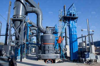
PATTERSON''s unmatched Ball and Pebble Mill custom design experience and manufacturing capability is your assurance of a system that meets your requirement for maximum grinding efficiency at a costeffective price. PATTERSON Batchtype Ball Pebble Mills ... ring gear and pinion drive, magnetic brake and inching device. Type "DJ" Jacketed Mills ...
The basic parameters used in ball mill design (power calculations), rod mill or any tumbling mill sizing are; material to be ground, characteristics, Bond Work Index, bulk density, specific density, desired mill tonnage capacity DTPH, operating % solids or pulp density, feed size as F80 and maximum ''chunk size'', product size as P80 and maximum and finally the type of circuit open/closed you are designing for.
Ball Mill Design A survey of Australian processing plants revealed a maximum ball mill diameter of meters and length of meters (Morrell, 1996). Autogenous mills range up to 12 meters in diameter. The lengthtodiameter ratios in the previous table are for normal applications.
STARTING TORQUE AND TIME CONSIDERATIONS The mill used for this comparison is a diameter by meter long ball mill with a 5000 HP drive motor. It is designed for approximately 90 per hour. This type twocompartment mill is a state oftheart shell supported cement finish mill.
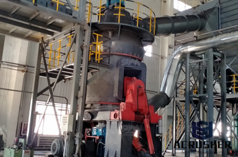
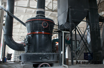
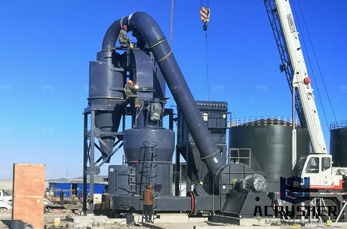
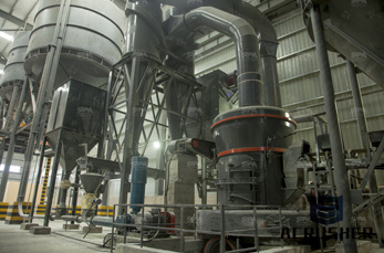
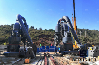
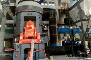
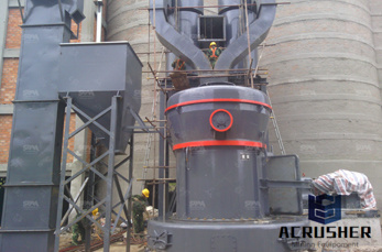
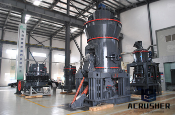
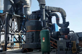
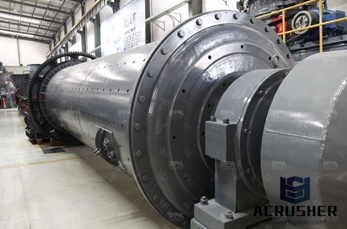
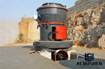
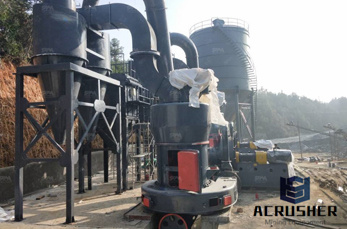
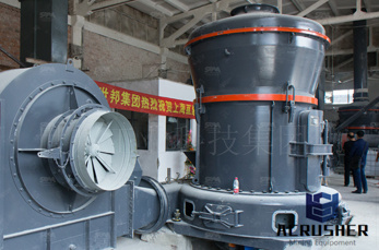
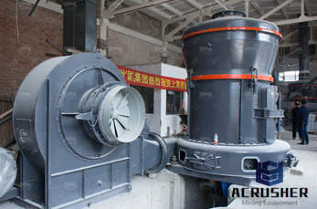
We bring forth a highly advanced Ball Mill, specifically engineered for both wet as well as dry cement grinding applications. Classified depending on the circuit design, bearing, grinding type and drive, the selection is made on the basis of the product fineness, quality, and nature of raw material, site conditions and specific requirements.
the mill is used primarily to lift the load (medium and charge). Additional power is required to keep the mill rotating. Power drawn by ball, semiautogenous and autogenous mills A simplified picture of the mill load is shown in Figure Ad this can be used to establish the essential features of a model for mill .
Ball milling is a size reduction technique that uses media in a rotating cylindrical chamber to mill materials to a fine powder. As the chamber rotates, the media is lifted up on the rising side and then cascades down from near the top of the chamber.
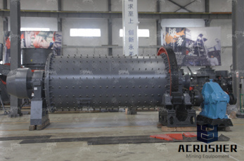
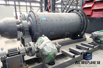
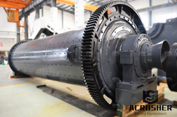
Ball Mill Operation. Ball mills ride on steel tires or supported on both ends by trunnions. Girth gears bolted to the shell drive the mill through a pinion shaft from a prime mover drive. The prime movers are usually synchronized motors. During rotation, a portion of the charge is lifted along the inside perimeter.
To ensure the stability of the mini ball mill, a ball mill base is design and fabricate to withstand the weight of the rotating jar, motor and gears. After a few hours, stop the mini ball mill and...
ball mill drive design. Ball Mill Application and DesignPaul O. Abbe. Slice Mills™ are identical to the Ball Mills and Ceramic Lined Mills in diameter and design The only difference is that they are as little as 12" in length. Since mill diameter dictates performance and mill length only affects capacity Slice Mills™ are used to develop or
The mill used for this comparison is a diameter by meter long ball mill with a 5000 HP drive motor. It is designed for approximately 90 per hour.
Ball Mill PINION SHAFT BEARINGS Pinion shaft bearings are of the SKF antifriction type mounted in a common twin bearing assembly. Bearings are fixed in place so that the pinion shaft of the mill is always in alignment with the drive components. Vbelt driven mills are furnished with an outboard bearing of similar construction.
Gearless mill drive (GMD) technology has further expanded the use of large SAG milling allowing to produce the world''s largest SAG mill of 42'' in diameter drawing power at 28 MW. Today, is the world leading supplier of gearless SAG mills operating globally.
The SAG mill is followed by two 20ft diam., 7,500hp geardriven ball mills. Another type of drive, less commonly used, consists of a motordriven speed reducer that is coupled to one of two ...
Design Method of Ball Mill by Discrete Element Method The spring coefficient in the tangential direction Ks can be obtained based on the defining equation for the Lame constant shown in (Eq. 8), which shows the rela tionship between the shear ratio and Young''s modulus for the substance.
The latter group includes the feed and discharge arrangement, the mill shell, the mill heads, the mill bearings, and the mill drive. In this module, we will cover all the maintenance detail, lubrication, inspection, and troubleshooting of the mechanical element of the ball mill.
Since for the ball mill design we are using 80% passing, the required value of C2 for the ball mill will be equal C3 is the correction factor for mill diameter and is given as; 𝐶𝐶3 = 𝐷𝐷 (3) However, it is important to note that C3 = vessel used in producing the ball mill was got from a
The Drive System Design Complete package of equipment Development of the drive technology for ball mill central drives within 50 years: 4 MW drive for a rpm mill. At the same time increasing the AGMA service factor from 2 to The weight is the system weight including couplings.
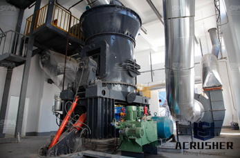
Figure 5. High–low wave ball mill liner Materials The selection of the material of construction is a function of the application, abrasivity of ore, size of mill, corrosion environment, size of balls, mill speed, etc. liner design and material of construction are integral and cannot be chosen in isolation.
Once you know the ideal speed of rotation for your mill jars, you will need to design your mill around this critical parameter. With most ball mill designs, you have two areas of speed reduction to tweak: from the motor drive shaft to the drive pulley and from the roller bar to the milling jar.
These large coal crushing drive systems are usually rotated by motordriven gearing. A typical application consists of a motordriven primary singlestage reducer that, through a flexible coupling, drives a large open pinion which in turn, meshes with a large ball mill ring (girth) gear that is attached directly to the ball mill.
3 Determine the design horsepower using the Design Horsepower formula (see below). 4 Based on your results, determine which belt section would be appropriate for your drive according to Figure 1 or Figure 2 (pg. 7). Narrow belt sheaves are more compact than Classical belt sheaves. Some belts are more appropriate for specific applications.
This project is to design and fabricate the mini ball mill that can grind the solid state of various type of materials into nanopowder. The cylindrical jar is used as a mill that would rotate the material that about to be ground, a motor is used to power the system so that the jar can rotate in high speed and using the regulator controls the speed of the rotation of the jar.
A practical case of ball mill foundation is examined herein. The diameter of mill is m with length of m, operating at 12 rpm. The height of mill shaft is m above ground.
WhatsApp)